Light guide design aid
Our Recommendation
Without too much effort (using optical simulation software such as LightTools or LucidShape), we design light guides with a few simple considerations to create visually appealing eye-catchers that can give a technical product a WOW effect. LightTools oder LucidShape) konstruieren wir Lichtleiter mit ein paar einfachen Überlegungen zu optisch ansprechenden Hinguckern, die einem technischen Produkt einen WOW-Effekt geben können.
We use 3D-printed components to validate the concept.
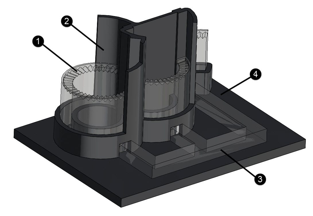
1 – The small bevelled surfaces ensure optimum distribution of light in the light guide. The point light source (LED) is reliably distributed in the light guide and becomes almost diffuse light. Although the lines of the bevelled surfaces are still slightly visible when illuminated, this can also be used as a design feature.
2 – In the example above, we had three different light sources. We used partitions to separate them from each other and ensure that they did not mix.
3 – The light guide with its three sections is designed as a component that can be inserted into the second mold for overmolding. The connecting bridges also help to position the light guide in the housing mold.
4 – Designed as a two-component component, it creates a watertight, visually appealing surface in the housing.
Injection-molded light guides – Design fundamentals
Light guides made of transparent plastic are used to transport or distribute light in a targeted manner. In product development, they require precise coordination between optical function, geometry, material selection, and injection molding feasibility.
1. Geometry: Guidance and loss prevention
Total reflection is key: The fiber optic cross-section must be selected so that the angle of incidence and reflection remains below the critical angle of the material.
Maintain bending radii ≥10x cross-sectional height to minimize scattering losses.
Prefer homogeneous cross-sections – abruptly changing geometries cause inhomogeneities.
Design light extraction specifically: Use microstructures, diffusers, or bevelled surfaces to distribute light specifically, rather than leaving it to chance.
2. Choice of materials: transparency and finish
PMMA (polymethyl methacrylate): Very high light transmission (~92%), sensitive to stress cracks, limited temperature resistance.
PC (polycarbonate): Slightly lower light transmission (~88%), but more mechanically robust and temperature-stable.
When selecting materials, pay attention to optical purity, low birefringence, and low water absorption.
3. Tool- and demolding-compatible design
Polished cavities required – matte or textured tool surfaces lead to scattering losses.
Plan for draft angles ≥0.5–1°, even on visually relevant surfaces.
Avoid undercuts – even the smallest recesses can cause visible defects (e.g., due to tension or streaks).
Place sprues outside optically active areas (ideally at the LED coupling point or in holding zones).
4. Tolerances and manufacturing stability
Optical fibers are functionally sensitive—even slight deviations can significantly impair light transmission.
Tight shape and position tolerances for coupling surfaces, especially for LEDs.
Minimize warpage and shrinkage by using suitable wall thickness ratios and flow path design.
Use simulation (optical and injection molding) to validate the design.
5. Manufacturing limitations
Maximum component length limited by tool size and filling behavior – segmentation may be necessary for large light guides.
Transparent plastics are often more viscous → Adjust the sprue and holding pressure strategy accordingly.
Material type, mold temperature control, and cooling time have a direct impact on optical quality – coordinate with your manufacturing partner at an early stage.